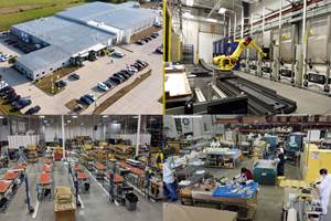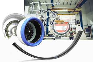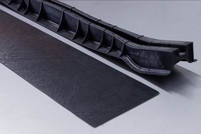
Source (All Images) | Greene Tweed
As the aircraft industry continues to strive for increased efficiency and sustainability, every pound of weight removed reduces fuel consumption and corresponding emissions. Composites have made significant progress in replacing heavier metallic components in aircraft engines, but more is still possible. For example, Greene Tweed (Lansdale, Pa., U.S.) has demonstrated the potential for its Discontinuous Long Fiber (DLF) materials to cut weight in complex-shaped parts by an average of 35% versus aluminum in more than 500 aircraft part numbers. However, to enable its use at the front of turbofan engines, the high-velocity impact behavior of DLF needed to be characterized to understand the effect of different composite constituents, meso-structures and possible hybridization with continuous fiber materials. The ultimate goal was to develop a design methodology and solution for improved impact resistance in such applications.
Impact resistance for DLF fan platforms
DLF thermoplastic composite (TPC) materials have successfully replaced metals in complex-shaped aerospace components for years, using aerospace-approved carbon fiber/PEEK prepreg unidirectional (UD) tapes that are cut into flakes and compression molded. These materials provide good chemical resistance, stiffness, high temperature capability and creep resistance above the glass transition temperature, as well as enhanced design freedom with the ability to integrate multiple parts into a single structure. Greene Tweed has invested in the characterization of quasi-static mechanical properties, or allowables, to support a design by analysis approach, including high-temperature strength, fatigue and creep data. However, the high-velocity (>100 meters/second) impact behavior of these materials — which form a sub-category of fiber-reinforced TPC — had not yet been substantially studied.
Rendering of Greene Tweed's aeroengine fan platform demonstrator for impact testing, featuring an internal center rib (orange) and stiffening gussets on the sides (blue) to reduce the unsupported region of its aerodynamic surface that would be subjected to hailstone impacts.
At the front of turbofan engines, fan platforms are components that cover the engine’s hub between the fan blades and direct airflow toward the low-pressure compressor. These have long been a target for Greene Tweed, potentially saving north of 8 pounds per engine versus metal. The complex geometries of these components, however, make it challenging to use traditional continuous fiber materials like UD tape, braid and fabric, although solutions do exist that use complex layups and 3D braids via processes similar to resin transfer molding (RTM).
Greene Tweed's aeroengine fan platform demonstrator made from Xycomp Discontinuous Long Fiber (DLF) thermoplastic composite materials.
Greene Tweed has demonstrated an alternative via its Xycomp DLF compression molding compounds, with the ability to rapidly manufacture highly complex parts using an automated and repeatable near-net shape process. This matched-die molding can also produce the smooth aerodynamic surfaces required for parts with airflow surfaces, while the use of a thermoplastic matrix greatly enhances recyclability from raw material to final parts.
Although Xycomp DLF is well proven — with close to half a million parts (including structural brackets, enclosures, covers, vents, doors, etc.) currently flying on 12 types of commercial aircraft — use in parts sitting at the front of an engine that are prone to hail impact damage is more challenging for a discontinuous fiber material. A prototype fan platform made with Xycomp DLF has long been known to meet typical mechanical requirements such as strength at max overspeed as well as dynamic performance requirements — except for high-velocity hail impact, where experimental results on coupons had been disappointing.
Researchers at Greene Tweed’s R&D Center for Composites (Yverdon, Switzerland) took on the challenge to understand the underlying behavior of this material when impacted at high speeds. The team launched a significant impact testing campaign on representative coupons evaluating different prepreg tapes and their constituents as well as hybrids combining continuous and discontinuous fiber-reinforced composites. Continuous fiber-reinforced composites included laminates and fabrics, while Greene Tweed’s internal research on discontinuous materials led to the use of a patented new chopped tape flake shape internally dubbed “DLF 2.0” (versus Greene Tweed’s standard 0.5 × 0.5-inch flakes). This notably increased impact resistance, prompting the fabrication of a demonstrator component that experimentally withstood the impact of a 2-inch hailstone hitting the part at 200 meters/second in its most critical location without any damage.
Exploring failure in plates
Greene Tweed's hail impact testing jig for DLF materials in plates (top) and in a demonstrator platform for aeroengines (bottom).
To characterize the impact behavior of its Xycomp DLF materials, Greene Tweed followed a building block pyramid approach, first testing plate coupons and then progressing to shaped demonstrators. Impacts were achieved using spherical, clear ice hailstones sized 2 inches in diameter, shot from a self-built hail impact testing jig. The tests were filmed by a high-speed camera capturing 10,000 frames/second to study the visually observable damage mechanisms on 6 × 12-inch, 0.15-inch thick plates that were inclined at 30° over the horizontal plane and pinned on the longer edges.
These plates were manufactured using UD tapes with a nominal volume fraction of 60% AS4 and IM7 carbon fiber reinforcing PA6, PEEK, PEKK, LMPAEK and PEI matrices, then cut into flakes to form Xycomp DLF materials. Two different AS4/PEEK materials with statistically identical quasi-static properties were tested to compare the potential effect of tape architecture while the baseline PEEK was also tested using S2 glass fiber. In addition, the baseline carbon fiber/PEEK material was cut with a novel “2.0” flake shape, as this had previously been shown to increase tensile strength in both quasi-static and fatigue testing by more than 50%. Continuous fiber laminates were also tested, including quasi-isotropic tape layups and cross-ply fabric layups. Hybrid samples tested were manufactured with continuous fiber materials on the “front” (impact facing) side and DLF on the back, as this is where shape complexity could be added to the production design. Finally, the effect of DLF plate thickness was studied on the reference material system.
Results from impact testing 6 × 12 × 0.15-inch-thick plates show resistance to 2-inch hailstone impact as a function of speed for various DLF constituent combinations.
The observed damage mode on DLF plates was always initiated by a tensile crack at the back of the plate, propagating from the impact location toward the top of the plate. Standard DLF is known to be notably weaker in tension than in other loading conditions. A high-velocity impact creates a local plate bending stress state below the impact location which, when it exceeds the tensile strength of DLF, logically leads to sample failure. This could be clearly observed on videos taken from the back of the impacted plates, where a local “tearing” of the material under the impact side could be observed while no damage of any kind could be seen at the front. Later validated in computed tomography (CT) inspections, this means that the sample geometry itself is somewhat ill-suited to showcase the real-life capability of DLF, because a real component would include a local stiffener to reduce the tensile strain in these critical part locations.
Regarding the effect of plate thickness, it appeared that each additional millimeter could add about 40 meters/second of additional impact resistance under otherwise similar test conditions. Changing from AS4 to IM7 carbon fiber did not improve impact resistance. Neither did hybrid constructions with continuous fiber materials on the impact face, further validating the critical damage mechanism previously identified. However, changing from carbon fiber to the S2 glass fiber option did improve resistance, as did using polymers with less crystallinity or continuous fiber reinforcement materials on the rear face (in tension) of tested samples, with DLF on the front face, even though such a layup would be of limited practical use.
Resistance of 6 × 12 × 0.15-inch-thick DLF coupons to 2-inch hailstone impacts, showing significant improvement of “DLF 2.0” featuring a novel flake shape.
The most striking change was obtained by using the novel flake shape (“DLF 2.0”). This patented change in geometry was brought about to reduce possible stress concentrations at the end of the composite flakes, thus increasing the apparent toughness of the material. Without changing anything else, the DLF 2.0 samples were found to exceed the hail impact resistance of continuous fiber laminates, including results obtained on a quasi-isotropic laminate made from the same base material as the modified DLF.
After evaluating all of the results, the team hypothesized that no single constituent parameter dominated the high-velocity impact behavior of DLF parts. Instead, the key parameter appears to be the composite’s apparent toughness, itself a function of the specific constituents paired and the interface achieved between them, as well as the tape’s meso-scale structure. The clearest proof of how much these intrinsic properties are interlinked is the very large increase in performance obtained by changing the flake geometry, and thus the part’s meso-structure. Despite the lack of predictability of such a material property, interesting generic trends could still be obtained in this study.
Platform demonstrator tests
Using results from the initial plate tests, an in-house-designed fan platform demonstrator was fabricated that closely approximated a real part for 25,000-35,000-pound thrust class engines. Among the design guidelines used, the Greene Tweed team limited the estimated part deflection upon hail impact to safe levels (as determined from the plate testing) by adequately stiffening the structure geometrically. This was done by strategically placing a central rib within the part and reinforcement gussets along its sides to limit the size of the unsupported region in the aerodynamic surface that would be impacted.
The rendering at left shows the five impact locations tested on demonstrator platforms with the most critical highlighted at top. Results from these trials of 2-inch hailstones impacting platforms made from various materials are shown here, where “MM” (far right on X-axis) denotes a change in molding parameters to make better use of the DLF 2.0 novel flake shape material.
Five impact locations were initially investigated, and without much surprise, the top right corner — which presented the largest unsupported region — proved to be the most critical. Once this critical location was defined, several of the key hybrid materials identified in the plate study were investigated. Thanks to the coupons study and the more fundamental understanding of DLF failure under high-velocity impact, the team was able to demonstrate that it was possible to achieve the hail impact resistance targets with the standard DLF material. Although performance was indeed higher with the modified flake geometry, being able to use the current DLF material in such applications is very welcome, removing the need to requalify a new material. Also important is the fact that Greene Tweed managed to derive sufficient design guidelines from the plate study to enable this improved impact performance. Still, the DLF 2.0 version remains an option for an application where even higher performance is required.
To ensure that nothing was missed, selected samples were scanned after impact using micro-CT. As with the initial testing on plates, it became clear that the predominance of a tensile failure mode induced by localized bending meant that no damage could be found in the bulk of parts that did not present visible damage at their surfaces. This is due to the highest strain in such a load case always being present at the outer surface of a part, ensuring that the critical location is easily observable.
Higher failure strength for future parts
As a result of this development effort to investigate and optimize DLF’s performance for high-speed impact and front-of-turbofan aeroengine applications, Greene Tweed has developed and explored a wide array of capabilities that now compliment its existing production infrastructure. Hybrid material combinations, geometrical optimization, nondestructive inspection/micro-CT and continued material development via DLF 2.0 are continuing to push discontinuous TPC into more aggressive and demanding applications.
Success for this research initiative was validated through the actual fabrication and testing of a DLF fan platform component made using the already-flying and certified AS4/PEEK carbon fiber material (Xycomp 5175), which solidifies competitive costing and ensures commercial viability. Xycomp DLF continues to offer weight, performance and cost savings compared to machined aluminum parts, with the aeroengine fan platform now proven as an example of such capability with sufficient impact resistance.
About the Author
Sebastien Kohler
Sebastien Kohler is a scientist working on thermoplastic composite materials in the Advanced Technology Group for Structural and Engineered Components at Greene Tweed (Lansdale, Pa., U.S.). He is based in the company’s R&D Center for Composites in Yverdon, Switzerland, and part of a cross-functional team developing new composite materials and novel molding processes alongside working on new applications, from ideation to final component. He holds a Ph.D. in mechanical engineering from the Swiss Federal Institute of Technology (EPFL) in Lausanne, where his thesis involved multi-scale experimental and numerical investigations of thin-ply composite materials.
Related Content
Braided thermoplastic composite H2 tanks with co-consolidated molded boss areas to fit EV battery space
BRYSON project demonstrates possible designs, automated manufacturing and low permeability concepts, including EVOH liner and novel PPA matrix.
Read MoreWelding is not bonding
Discussion of the issues in our understanding of thermoplastic composite welded structures and certification of the latest materials and welding technologies for future airframes.
Read MorePlant tour: Sekisui Aerospace, Orange City, Iowa, Renton and Sumner, Wash., U.S.
Veteran composites sites use kaizen and innovation culture to expand thermoplastic serial production, 4.0 digitization and new technology for diversified new markets.
Read MoreThe potential for thermoplastic composite nacelles
Collins Aerospace draws on global team, decades of experience to demonstrate large, curved AFP and welded structures for the next generation of aircraft.
Read MoreRead Next
Optimized approach to predict delamination failure in CFRTP structures
ARRK Engineering and Mitsui Chemicals improved delamination prediction accuracy to help optimize absorbed energy/failure load for an overmolded TAFNEX CF/PP UD tape bumper beam.
Read MoreDetermining steel/composite failure load of bonded repair assemblies
Bureau Veritas and partners use a novel equivalent interface test specimen and simulation to predict failure load in bonded composite patch repairs to steel structures.
Read MoreCutting 100 pounds, certification time for the X-59 nose cone
Swift Engineering used HyperX software to remove 100 pounds from 38-foot graphite/epoxy cored nose cone for X-59 supersonic aircraft.
Read More


