Share
Read Next
Source | , Chris Hanoch, Lockheed Martin (left and bottom right) and Darin Russell, Lockheed Martin (top right)
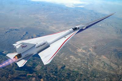
The X-59 is an experimental jet aircraft designed and built by (Palmdale, Calif., U.S.) and used by NASA to perform research as part of its mission to reduce sonic booms from supersonic aircraft. Swift Engineering Inc. (San Clemente, Calif., U.S.) was contracted to build the aircraft’s 38-foot-long nose cone, designed to control aerodynamic pressure waves (shock waves) that form at the tip during supersonic flight. But first, Swift needed to work with the Skunk Works to take its preliminary design — featuring a sandwich construction of honeycomb core with carbon fiber-reinforced epoxy skins — and complete the nose cone’s structural sizing, analysis and test validation.
Read more about the X-59’s design, manufacture, assembly and testing.
To do this, it used HyperX software from Collier Aerospace (Newport News, Va., U.S.), which enabled cutting the nose cone’s weight by more than 25%. It also enabled Swift Engineering to evaluate the design for a wide range of load cases, perform detailed failure analyses using allowables data and optimize for manufacturability. “The only way we were going to meet the tight project deadline was to automate the stress analysis,” says Bill Giannetti, technical consultant for Swift Engineering. “I knew the HyperX software could do that and would also generate the report that we would need to get this structure certified for flight.” Indeed, Giannetti’s team was able to not only meet the mass reduction requirements but also delivered the nose cone ahead of schedule and under budget.
Reducing the boom and weight
While this article was being drafted in early summer 2025, the X-59 was undergoing ground testing in preparation for the first flight of multiple flights. Its mission is to collect data to help establish an acceptable noise standard for commercial supersonic flights by aircraft like the XB-1 from Boom Technology (Centennial, Colo., U.S.), which is already moving toward production. Thanks to the X-59’s elongated nose cone, it is expected to significantly reduce noise impacts from supersonic flights.
Swift Engineering’s contract to design the nose cone in 9 months and build it in 6 months started during a meeting with the Skunk Works. “I had been working with Swift Engineering for about 8 years and was a technical fellow in the structures group at the time,” says Giannetti. “After their program manager reviewed the objectives, he emphasized that for each pound of mass we could remove from the nose, they could remove 3 pounds from the X-59 tail to optimize the center of gravity. I brazenly said that not only could we complete the structural design optimization on time, but we’d pull 100 pounds out of their 400-pound original design. However, they would then have to give polo shirts with the Skunk Works logo to the whole engineering team. He agreed.”
Swift Engineering’s process flow for design, analysis and substantiation of the X-59 nose cone, noting that HyperSizer and Hypermesh are now contained in HyperX. Source | Swift Engineering
“Our timeline was pretty ridiculous,” he continues. “But I knew we could do it with HyperSizer, which was the name of one of the products in the Collier suite at the time. We’d take their finite element [FE] model and put our specific nose configuration on it. Then we’d run all the load cases and mine that data for the critical load cases, refine our model and then run HyperFEA, which takes your final analysis results and inputs them into HyperSizer to rebuild the model cards. We’d then rerun the FEA and keep doing that until we hit the required safety margin at the minimum mass. I knew the software would also generate the final certification level report needed. This was the only way we were going to meet the deadline. However, pulling the mass out of the structure would be another thing entirely.”
Sizing, hitting 60% of mass target in first pass
One of the Swift Engineering team’s first issues was that the 32-foot-long configuration originally presented was actually 38 feet in the CAD file they received. “We took it in stride and began our workflow,” says Giannetti. “We converted the original design using a solid laminate with a single bulkhead to a minimum-gauge honeycomb structure with multiple bulkheads. With that approach, we felt we could pull mass out of the structure and still meet the stringent waviness and deformation requirements. The structure needed to be extremely stiff.
“We then set up the model, representing both facesheets and the core with a single plane of shell elements, and got our 270 critical load cases. We built out the FEA and ran the load cases. We pulled all the stresses and then we took that and set it up in HyperSizer and developed our panel sizes, which is one of the key steps in the integration of HyperSizer. We loaded all our material cards and all our bulkheads and gave it a range of laminates to choose from. We then hit the solve button and we were able to pull out probably 60% of our 100-pound mass reduction goal with just our first pass.”
Materials, final 30-pound reduction
Due to the tight timeline, Giannetti’s team picked a material that had a fully defined set of material allowables. “We needed to pick a material that was already qualified because we didn’t have time to test anything,” he explains. That material was Toray Composite Materials America (Tacoma, Wash., U.S.) 2510 prepreg with T700S standard modulus carbon fiber in a toughened, 250°F cure epoxy resin with a public , which Toray notes is formulated for out-of-autoclave (OOA) processing of aerospace primary structures.
The team then performed a series of sizing optimization steps, says Giannetti, “but we weren’t getting to 100 pounds of mass reduction. So, we used a feature in HyperSizer that typically helps determine the optimum number of ribs in a wing. It basically starts with a given spacing and then iterates until you come up with a mass-optimized structure. There will be an optimum configuration for the set of loads, material and structural properties and safety margins you’re trying to achieve. We used that to define the quantity, size and location of the bulkheads that would allow us to have a mass-optimized structure. We basically took a wing concept and applied it to the nose. And that got us another 10% mass savings. But we still had another 30 pounds to go.”
Giannetti and his team discussed their options. “We were using a symmetric sandwich of three plies-core-three plies with 1/8-inch-diameter cell for the 3 pound per cubic foot Nomex honeycomb core,” he says. “Looking at that structure, I thought we could eliminate the innermost ply and that would pull out about 30 pounds. So, we went to a construction of three plies outer skin, core and two plies on the inner skin. We hit our target, and our guys got the polo shirts.”
Failure criteria, validation testing
Giannetti notes Swift Engineering also made the delivery in record time, “and we submitted what the company considered was a class-defining report using HyperSizer. Every single bolt — we bonded and bolted the bulkheads — had a margin for bearing and the properties used included elevated and sub-ambient temperature for buckling. We used hot/wet open hole compression [OHC] properties as the defining failure criteria. Those are the most conservative properties, and that allowed us to address fatigue requirements, because we used the maximum OHC strain as a sizing strain. We then compared the principal strain to that value and that gave us our safety margin. It’s a little bit conservative, but it covers us for fatigue, random vibration and for all those secondary long-term effects and requirements.”
Swift Engineering then built a full-scale 300-pound, 38-foot-long structure and completed testing to validate the design. “They did vertical deformation testing where they basically pushed it up, down, left and right to see if they could hear any kind of strain relief or cracking,” says Giannetti, “which you typically hear during such tests using acoustic emission. It was silent and hit all the marks. Our numbers were right on, and we were very excited about that.”
Checking all load cases, failure analyses
Collier Aerospace was founded by Craig Collier. He explains that HyperSizer was first developed 30 years ago, and has now been replaced with HyperX. “It has a different look and feel and is more powerful,” he says. “From a computational perspective, it’s multi-threaded and multiprocessed. HyperX maintains all the same functionality but is a completely new code base and true next-generation software, not just upgraded.”
“I worked on the B2 bomber in the 1980s,” he says. “Although we were confident about our calculations, there just wasn’t time to check for every possible load case. We had to filter down to what we thought were the critical load cases for different areas. And from those, we again couldn’t necessarily do all the failure analyses because we didn’t have time. So, we did those we thought were most controlling. At Collier Aeropsace, our vision over the years has been to enable extremely fast computational capability using high-performance computing so that we can process all of the external loads on the vehicle without having to make an assumption as to which ones are critical. And for each one of those, we process all the failure analyses. But we also include traceability, where at any point you can drill down and inspect every intermediate calculation to verify that the input data that’s coming in is what you approve.”
He notes that HyperX also enables companies to customize how they want to do their analysis for certification. “They pair their allowables approach with their failure analysis approach,” says Collier. “HyperX can be used by a large group of people ensuring that everyone is using it consistently and that’s part of the whole certification by analysis approach. You’re also using consistent data allowables throughout all of the failure analysis which provides interactive traceability.”
Updating the design for load convergence
Collier explains that HyperX is FEA-code agnostic. “We can use leading FEA programs like Nastran and Abaqus to extract results from the model and then perform the failure analyses simultaneously, exploring different laminate options or core densities or core depths to reduce any of the potential failures that may happen.”
“However, you also have to iterate with an FEA solver to converge the load path as you change the structures,” he notes. “Our software updates the FEM with the correct terms of the material system’s stiffness matrix in the laminates, and that’s also part of the ability you must have if you want to certify by analysis. You must not only have good failure criteria but be able to interact with your final model in an appropriate way.”
Source | Collier Aerospace
Giannetti emphasizes how significant this is. “You need to include the process of updating the FEM with the new design and iterate with the FEA solver to get load path convergence,” he explains. “When you make a change to the model or change the structure, then the load distribution in the structure changes. And your last optimum design perhaps now doesn’t have a thick enough laminate while in other places it’s not thin enough. So, you make those changes and put that back into the FEM to get the new load paths. But you have to do that in the correct way, and HyperX is very good at updating the FEM so that on the next iteration it gets the correct FEA internal load path, which then allows you to get the correct safety margin calculation.”
Compressing the cycle to certification
“If we had used a similar approach as with the nose cone, we could have probably done that work with 10% of the people in half the time.”
Giannetti gives an example of how this software package also compresses the engineering cycle to certification. “I was on a team of 60 engineers that took over 1 year to do a similar type of analysis as this nose cone but instead for a helicopter flight structure. We were required to use a different approach, using the FEA to generate loads and then use those loads in another piece of software to basically hand calculate all the stresses and margins. We ended up analyzing over 900 components, and if we had used a similar approach as with the nose cone, we could have probably done that work with 10% of the people in half the time.
“Finally, at the very end of that process is the stress report,” he continues, “where we are able to show every single failure analysis margin of safety with all the inputs and outputs for every location in the vehicle. Full-scale testing is still going to be required, but the ability to have a better process for making sure that nothing gets omitted, that everything that could possibly go wrong is investigated and evaluated — you can’t afford to do that with physical tests.”
Giannetti notes HyperX has a new graphic user interface (GUI) with a more ordered structural tree. “In the past with FEA, everything was commands and written into blocks,” he notes. “The new GUI uses icons for features that allow you to quickly drill down versus a mass of commands, which gives the user more power. It’s more logical and faster to use, enabling an even more optimized workflow.” He adds that Collier’s software has saved him countless hours, not just in automating analysis, but also in the final reports for certification. “Engineers shouldn’t have to write reports. They should be able to just hit the report button. And that’s what HyperX provides.”
Related Content
Co-molding SMC with braided glass fiber demonstrates truck bed potential
Prepreg co-molding compound by IDI Composites International and A&P Technology enables new geometries and levels of strength and resiliency for automotive, mobility.
Read MorePlant tour: Teijin Carbon America Inc., Greenwood, S.C., U.S.
In 2018, Teijin broke ground on a facility that is reportedly the largest capacity carbon fiber line currently in existence. The line has been fully functional for nearly two years and has plenty of room for expansion.
Read MoreRevisiting the OceanGate Titan disaster
A year has passed since the tragic loss of the Titan submersible that claimed the lives of five people. What lessons have been learned from the disaster?
Read MoreThe potential for thermoplastic composite nacelles
Collins Aerospace draws on global team, decades of experience to demonstrate large, curved AFP and welded structures for the next generation of aircraft.
Read MoreRead Next
CIRA qualifies CMC structures for the reusable Space Rider
Italian team designs, builds and tests multiple large, complex thermal protection system structures made from patented ISiComp C/C-SiC ceramic matrix composites.
Read MoreDigital design, multi-material structures enable a quieter supersonic NASA X-plane
NASA’s composites-intensive X-59 QueSST experimental aircraft is set for its first flight by the end of 2022, after nine years of design, manufacture, assembly and testing by Lockheed Martin Skunk Works.
Read MoreUsing multidisciplinary simulation, real-time process monitoring to improve composite pressure vessels
Multi-pronged approach closes the loop between design and production of Type 3, 4 and 5 pressure vessels, enabling simulation of as-built composite tanks to improve performance and storage capacity while reducing weight and cost.
Read More


