


The main objective of the project FRAMES, which began in July 2020, is to validate a manufacturing approach being used to produce the Advanced Rear End Demonstrator manufactured by the German Aerospace Center (DLR) as part of the CS2 technology platform for large passenger aircraft (LPA). This demonstrator aims to bring reliable and competitive solutions for simulation of heating during automated fiber placement (AFP) to achieve high-rate manufacturing of thermoplastic stiffeners and self-heated tooling to support co-consolidation of a skin-stiffener assembly.
For more context of how FRAMES fits into the objectives of the Advanced Rear End Demonstrator project, see the last section of this article.


Optical thermal modeling of xenon flashlamp heating system
AFP of carbon fiber-reinforced thermoplastic (CFRTP) composites has mostly relied on laser heating to achieve the high temperatures needed for processing high-performance thermoplastic matrix materials such as PEEK (polyetheretherketone), PEKK (polyetherketoneketone) and LMPAEK (low-melt polyaryletherketone). However, a new technology has emerged that is based on a pulsing xenon flashlamp. In this method, high-energy, short-duration pulses delivered by a powerful broadband heat source are collected and delivered by a quartz light guide. Positioned near the nip point of the AFP head, the quartz light guide shapes and positions the light energy to heat the substrate and incoming tows before consolidation is achieved under a compaction roller. This xenon flashlamp system has been shown to match the rapid response time of a laser and reach the temperatures required to process thermoplastic composites.
During AFP processing, the xenon flashlamp pulse must be controlled to account for changes in speed and geometry and maintain a target temperature. This is achieved by varying flashlamp pulse energy, duration and frequency. To optimize these parameters, an opto-thermal simulation model has been created that uses optical ray tracing techniques (calculating the angle of refraction/reflection at each surface) to characterize the flashlamp source, as well as finite element analysis (FEA) to predict the resulting processing temperature. Using these simulation tools, trial-and-error can be avoided; pulse parameters can be chosen to achieve a desired processing temperature without the expensive and time-consuming physical trials.
Heraeus Noblelight (Cambridge, U.K.) is leading the development of the optical thermal model applied to its Humm3 flashlamp system. The process to create a reliable simulation involves the optical characterization of the xenon flashlamp source using goniometric (rotation about an axis) measurements and spectral irradiance (light energy received by the surface) measurements which are then used to determine the spectral energy levels, spatial distribution and electrical-to-radiative energy efficiency of the source.
Measuring spectral energy
Fig. 1 below shows the experimental setup devised to determine the energy emission of an xenon flashlamp with respect to wavelength using spectral irradiance measurements. In this system, the light from the xenon flashlamp goes into a detector at a preset distance away (typically 0.5 to 1 meter, at left below). That light is then transported via an optical cable into a double-monochromator system (at bottom left below) which determines the light intensity at a specific wavelength. This results in a detailed spectral irradiance plot of the light source — in this case, the entire emission curve of the xenon light energy from the Humm3 flashlamp is measured (Fig. 2).
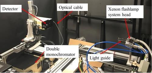
Fig. 1. Double monochromator test setup used for spectral irradiance measurements. Light from the xenon flashlamp (upper right) goes into a detector (upper left) which transports it via an optical cable into a double monochromator which measures the light intensity at a specific wavelength. This enables a detailed plot across the spectrum of the flashlamp’s emitted light energy. Photo Credit: Heraeus Noblelight
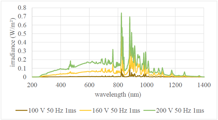
Fig. 2. Spectral irradiance measurements of light exiting the Humm3 xenon flashlamp. Photo Credit: Heraeus Noblelight
Measuring energy efficiency
Fig. 3. Schematic of the integrating sphere used for spectral radiant power measurements. Photo Credit: Heraeus Noblelight
System efficiency has also been evaluated using an integrating sphere (Fig. 3) at the Heraeus laboratory in Hanau, Germany to accurately determine the spectral energy exiting the Humm3 light guide at different voltage levels. The sphere features a highly reflective diffuse surface that directs virtually all the optical energy exiting the flashlamp head to a double monochromator detector. By modulating the pulse energy for a given pulse duration and frequency, the average optical power exiting the Humm3 head is measured as a function of wavelength for a range of flashlamp voltages.
Analyzing angular energy distribution
The position of the flashlamp head relative to the AFP head nip point is also a critical aspect for achieving a high-quality composites layup. In parallel to measurements of output power, the variation in xenon flashlamp light intensity with respect to its angle from the source has been measured. All measurements were normalized to investigate angular energy distribution rather than absolute power output at this point. Those results were used to validate a ray tracing simulation of the flashlamp to predict how the energy of the flashlamp pulses are distributed between the substrate, nip point and incoming tows.
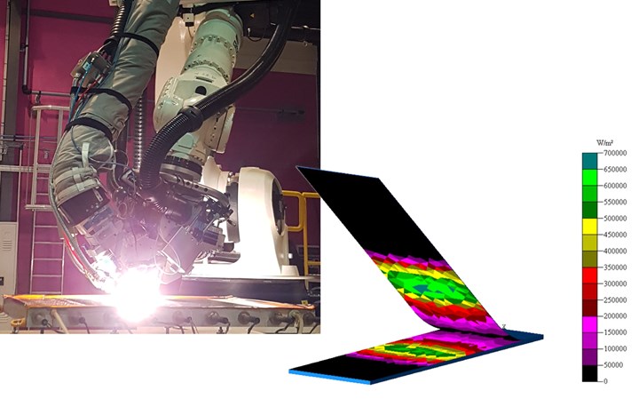
Fig. 4. Result from optical model using TracePro software. Photo Credit: Heraeus Noblelight
The optical ray tracing analysis (Fig. 4) — achieved using TracePro software (Lambda Research Corp., Littleton, Mass., U.S.) — is then detailed to calculate surface irradiance profiles on the composite tow and substrate. These irradiance profiles are used as input boundary conditions for the thermal simulation. Optical and thermal behavior of carbon fiber-reinforced LMPAEK tapes has also been characterized to feed the model at the relevant processing temperatures.
Validation via physical trials
As a validation step, physical AFP trials have been performed at Compositadour (Bayonne, France) to show the ability of the simulation to predict the temperature values seen during actual AFP layup. Infrared thermography and embedded thin thermocouples inside composite layups were used to measure processing temperatures during the AFP trials. Measurements appear to show reasonable agreement with predicted temperature profiles in the region to close the nip point and also through the thickness.
These measurements, however, also highlight the influence of tooling on the thermal management for the first few plies. At the beginning of the layup, the first few plies are very close to the tool surface, which can act as a heat sink. For this reason, heated tooling has been used. The tool temperature has a strong influence on the AFP nip point temperature.
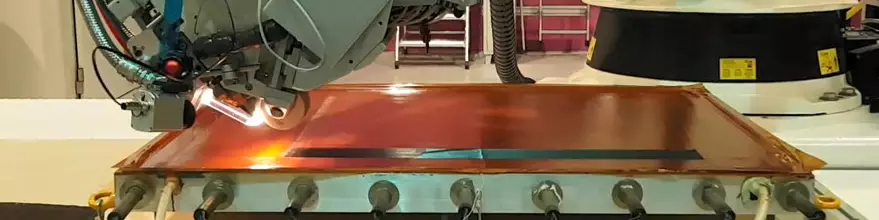
Fig. 5. Thermoplastic layup trials with Humm3 xenon flashlamp heating system at Compositadour. Photo Credit: Compositadour
During this beginning phase of layup, pulse parameters for the xenon flashlamp need to be adjusted to keep nip point temperature constant. But once few plies are laid up, the layup starts to become a kind of insulating layer and the influence of tool temperature decreases. At this point in the process, there is no need for further pulse parameter adjustments.
During the FRAMES project validation trials, heated tooling has been used to evaluate different processing temperatures during AFP, explains Guillaume Fourage, chief engineer for composite projects at Compositadour. “The manufacturing approach for the advanced rear end demonstrator is not yet frozen and we are evaluating different options for the skin layup with the aim to find the right balance between process time, energy consumption and layup quality. Changing the tool surface temperature requires us to adjust the pulse parameters accordingly to reach the proper nip point temperature. This is part of the development plan of the optical thermal model and helps us to increase reliability and robustness of the simulation under different layup conditions.”
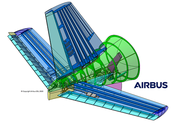
Thermoplastic composite Advanced Rear End (ARE) demonstrator for Clean Sky 2. Photo Credit: (top) Airbus, (bottom) ESTIA-Compositadour
This simulation model is now being adapted to the final heating system and tooling configuration that will be used to manufacture the CS2 thermoplastic composite Advanced Rear End (ARE) demonstrator. Parts are being manufactured in 2021 for assembly in 2022 with the goal of reaching TRL 6 by the end of the project in 2023. In parallel, a manufacturing readiness level (MRL) of 5/6 is being pursued, not only for the ARE demonstrator, but also for the associated manufacturing processes and tools that are being developed. Overall goals of the ARE demonstrator project include: Reduce costs by up to 20%, component weight up to 20% and fuel burn by up to 1.5%, as well as improve aerodynamics in line with Clean Sky’s environmental objectives.
This project has received funding from the Clean Sky 2 Joint Undertaking (JU) under grant agreement No 886549. The JU receives support from the European Union’s Horizon 2020 research and innovation program and the Clean Sky 2 JU members other than the Union.
For more information, contact Guillaume Fourage, g.fourage@estia.fr
Related Content

Carbon fiber, bionic design achieve peak performance in race-ready production vehicle
Porsche worked with Action Composites to design and manufacture an innovative carbon fiber safety cage option to lightweight one of its series race vehicles, built in a one-shot compression molding process.
Read More
Sulapac introduces Sulapac Flow 1.7 to replace PLA, ABS and PP in FDM, FGF
Available as filament and granules for extrusion, new wood composite matches properties yet is compostable, eliminates microplastics and reduces carbon footprint.
Read More
The potential for thermoplastic composite nacelles
Collins Aerospace draws on global team, decades of experience to demonstrate large, curved AFP and welded structures for the next generation of aircraft.
Read More
Otto Aviation launches Phantom 3500 business jet with all-composite airframe from Leonardo
Promising 60% less fuel burn and 90% less emissions using SAF, the super-laminar flow design with windowless fuselage will be built using RTM in Florida facility with certification slated for 2030.
Read MoreRead Next

Scaling up, optimizing the flax fiber composite camper
Greenlander’s Sherpa RV cab, which is largely constructed from flax fiber/bio-epoxy sandwich panels, nears commercial production readiness and next-generation scale-up.
Read More
Ultrasonic welding for in-space manufacturing of CFRTP
Agile Ultrasonics and NASA trial robotic-compatible carbon fiber-reinforced thermoplastic ultrasonic welding technology for space structures.
Read More
Cutting 100 pounds, certification time for the X-59 nose cone
Swift Engineering used HyperX software to remove 100 pounds from 38-foot graphite/epoxy cored nose cone for X-59 supersonic aircraft.
Read More