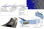
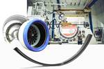
Completion of the 8-meter-long thermoplastic composite (TPC) fuselage section comprised continuous ultrasonic welding of the MFFD’s right-hand (RH) longitudinal fuselage joint (left) and resistance welding of upper and lower fuselage frames (right). Source | AIMEN, and for all images, Clean Sky 2 MFFD, MultiFAL and WELDER projects
The Multifunctional Fuselage Demonstrator (MFFD) is a Clean Sky 2 (now ) project spanning roughly 10 years that has produced the largest aircraft structure — an 8 × 4-meter-diameter fuselage section — completely fabricated from thermoplastic composite (TPC). Furthermore, its myriad components are welded together, aimed to demonstrate “dustless assembly,” which could eliminate the multistep process chain, labor, time, cost and weight of drilling holes and installing fasteners in composite primary structures.
CW has reported on this project for years via multiple articles and news releases. As explained in CW’s 2023 article, “Manufacturing the MFFD thermoplastic composite fuselage,” assembly of the MFFD’s lower and upper shells began with the left-hand [LH] side butt-strap longitudinal fuselage joint. That work was completed in the BUSTI project, as announced in March 2024, where the 8-meter-long join was achieved using a CO2 laser-based continuous joining technology called CONTIjoin (see ), developed by the Fraunhofer Institute for Material and Beam Technology (IWS, Dresden, Germany).
Following CONTIjoin, the last steps to complete the MFFD assembly included welding the right-hand (RH) overlap joint using continuous ultrasonic welding. Finally, fuselage frame couplers in the upper and lower halves were resistance welded to achieve continuous structures across both LH and RH joints.
As explained in my 2020 blog, “,” the welding techniques used in the MFFD’s various assembly steps were decided early on. “MFFD will demonstrate many technical approaches,” noted Ralf Herrmann, Airframe R&T Typical Fuselage at Airbus Operations GmbH (Bremen, Germany) and leader of the MFFD program, “so it is not the same as in manufacturing an actual fuselage, but instead is designed as a vehicle for demonstrating and maturing technologies.”
The RH overlap joint and welding of the fuselage frames were completed within the MultiFAL (2019-2023) and WELDER (2021-2023) projects by leading partners (Madrid, Spain), (O Porriño, Spain) and the (Zaragoza, Spain) with help from ultrasonic equipment supplier Dukane (Saint Charles, Ill., U.S.) via its subsidiary in Prague, Czech Republic, and production automation specialist (Fulda, Germany). This article will walk through the MFFD’s final assembly steps and the technology required for their success.
MultiFAL and WELDER projects
For both of these projects, Airbus was the Clean Sky topic manager and The CT Engineering Group was the consortium coordinator. MultiFAL was also managed by Fraunhofer Institute for Manufacturing Technology and Advanced Materials (IFAM) in the Research Center CFK NORD (Stade, Germany), where final assembly of the MFFD would take place.
“We were tasked with developing and supplying the automated system for joining the upper and lower fuselage halves,” says José Maria Rodríguez Valenzuela, R&D project manager at CT Engineering. He explains the purpose of MultiFAL was to reuse a Fraunhofer IFAM prototype assembly station, integrating hardware and control systems for the necessary positioning and welding operations. The consortium also included FFT and AIMEN, which developed an online monitoring system. The 3DExperience platform from software supplier Dassault Systèmes (Vélizy-Villacoublay, France) enabled the collaboration between the team and stakeholders to support CAD/CAM, assembly and simulation.
“The first goal was to design and propose some concepts to the topic manager for the assembly facility according to the requirements,” says Valenzuela. “IFAM and Airbus then selected the preferred concepts, and we designed the facility [the assembly platform and system] into which the fuselage halves would be installed based on analysis of the stress and all the process loads during welding. We then proceeded with manufacturing the facility with its positioning systems. First, we prepared a digital mockup of the assembly process in our design. The result is not only the facility’s steel structure, but also FFT’s control system for the welding end effectors that would be integrated later during the WELDER project, as well as all of the mechanics of the operations and tolerances required. We had to consider not only the assembly of the fuselage shells but also the activities of the operators, including how to provide access platforms and the necessary mechanisms and software to manage the various placement, welding and measuring activities.
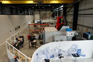
Figure 1. The MFFD in the automated assembly facility developed in the MultiFAL project. Source | AIMEN
“Airbus and its partners were designing the upper and lower fuselage shells at the same time we were developing the designs for the automated assembly facility,” continues Valenzuela. “Two years later, we started the WELDER project.” The main objective for WELDER was to design, develop and deploy two robot-based, modular and flexible welding solutions, including tooling and auxiliaries, for completing the 8-meter-long RH fuselage joint and subsequent connection of upper and lower fuselage frames across the RH and LH fuselage seams. AIMEN developed the end effector for continuous ultrasonic welding of the fuselage joint, working with ultrasonic equipment supplier Dukane. Meanwhile, Aitiip designed and built the resistance welding end effector as well as the required TPC couplers for joining the fuselage frames. “These parts had different geometries, made using a hot forming press,” says Valenzuela. “They were trimmed and delivered to Germany along with the welding tools to be installed in the MultiFAL assembly station [Fig. 1]. We then installed the ultrasonic welding end effector on an external linear axis and the resistance welding head on a linear axis inside the fuselage.”
“We led the development of the welding, including the system setups and lots of coupon tests to define the process window and optimal parameters for both processes,” says Dr. Elena Rodriguez, head of advanced composites technologies at AIMEN. “We also collaborated with Aitiip for the heating elements in the resistance welding and provided the online monitoring system to capture the data for both types of welding operations.”
Welding the RH longitudinal joint
In ultrasonic welding, a sonotrode sends vibration through a TPC laminate to create heat at the weld interface, but this typically requires an energy director — a layer of unreinforced resin, traditionally with triangular protrusions, to help focus the energy — between the two parts being welded. Although ultrasonic welding is well-developed for spot welding, it is much less mature for continuous welding, notes Dr. Massimiliano Russello, team leader of composites welding at AIMEN. He notes there were numerous challenges in developing a continuous ultrasonic welding process for the final MFFD fuselage joint, including developing a continuous process for such a long weld (8 meters) and also how to achieve the overlap joint design.
Figure 2. The RH longitudinal joint was welded in three steps, or passes, each with a different thickness and optimal set of parameters. The diagram at top also shows TPC couplers for welding the upper and lower fuselage frames. Source | AIMEN
“We finally decided to do this in three steps,” says Rodriguez. These three steps, or three passes of the welding tool, enabled joining the stepped laminates in the upper shell to the stepped laminate in the lower shell (Fig. 2), but the process parameters were different for each. “It was a challenge to design a tool that could weld all three steps while ensuring contact pressure and stability between the parts. Also, the continuous welding machine we had at lab scale was limited to less than 1 meter, so we had to work on parametrization of the process to scale it up.”
“And to use it in a continuous mode for the high-temperature TPC materials used in the MFFD — [mainly Toray Advanced Composites (TAC, Nijverdal, Netherlands) unidirectional (UD) tapes of carbon fiber-reinforced LMPAEK polymer from Victrex (Clevelys, U.K.)] — in such large and thick parts was especially a challenge,” adds Russello. “To weld the upper shell to the lower shell in a continuous and fast way, we had to weld from only one side and use the three different passes with different thicknesses, up to 3.5 millimeters. And the greater the thickness, the more difficulties we had in the welding.” This is because it’s difficult to vibrate a very thick part and have the vibration propagate to the weld interface.
The ultrasonic welding head (center) with roller on right and cooling/consolidation block on left. Source | AIMEN
Welding end effector. In addition to the ultrasonic head, a roller on the right ensures the parts are in contact and a cooling or consolidation block on the left applies pressure on the part after heating for consolidation (Fig. 3), explains Russello. “That block also absorbs heat coming from the weld interface.” In the final ultrasonic welding head, the aluminum cooling block was replaced with a copper block for higher conductivity and heat absorption, resulting in much higher surface quality.
Parameters and scaling the process. There are many parameters that affect the welding process, including pressure, ultrasound amplitude, time and cooling. Also, the layup, conductivity and thickness of the part are important. These all affect the temperature distribution, heating behavior and energy dissipation — a complex, interrelated mechanism that is constantly developing during the process, says Russello.
“We started at lab scale with a very simple setup, and then scaled in complexity to have the final welding head that we integrated into the MultiFAL facility,” he continues. “Starting at lab scale, we installed monitoring systems, including thermal cameras and temperature sensors, and did a long study of all the different parameters, including numerical models to understand the effect on temperature development and weld quality, and how we could use the monitoring system to ensure quality.
“We then moved to a medium scale, where we welded 2-meter-long strips to validate and compare versus what we had at lab scale,” says Russello. “We calibrated the parameters and performance on the 2-meter panels, where the welding looked very good, and these were tested mechanically and with NDT. Using the monitoring system, numerical models and simulation, we could then correlate to the full-scale demonstrator. We were able to show the parameters for the medium scale were also valid for the entire fuselage section, which was a very key result.”
Temperature control. The next challenge was to have a well-designed head temperature control. During continuous welding, explains Russello, “the welding time depends on the speed at which you’re moving the welding head.” Note, this includes cooling, which must fall within a precise window to develop the necessary crystallization in the LMPAEK polymer for mechanical strength. “But you also cool actively during movement, which means that the cooling rate depends on the way you move the welding head,” notes Russello. “So, if you move faster, you have less time to cool down the part. Either you have to optimize the parameters or reengineer the cooling because you need that speed for welding. It’s all interconnected.”
For the MFFD, the AIMEN team welded from the external side of the fuselage. But inside, there were metal holding blocks to prevent movement during the pressure application that would also extract heat from the components being welded. And this comes back to the three welding steps or passes, and how each required different parameters. “When the back laminate being welded is very thin,” says Russello, “the heat easily goes into the holding block. But at the topmost, thicker step, it takes longer to transfer the weld heat to the blocks and this means that if you don’t provide enough cooling, the weld will delaminate in this area.”
“By simply analyzing the temperature after the cooling block,” he continues, “we were able to understand how the part would behave after welding. When the temperature was below 145°C, we never achieved consolidation of the part. But when the temperature went above 150°C, we were experiencing some delamination. By monitoring the temperature after the consolidation unit — which was on the surface, not at the weld interface — and calibrating that to the process parameters, we were able to ensure that we achieved sufficient cooling and avoided delamination after welding.”
First-time right. “Ultrasonic welding is very efficient and fast compared to other technologies we have investigated,” says Russello, “but it was difficult to complete this fuselage weld in one shot, first-time right without having previous historical information.”
Valenzuela agrees, emphasizing, “We had only one chance to make the weld for each step, and even though AIMEN performed so many tests to define the parameters, when the team went to weld the MFFD, the laminate in the upper shell was not what they expected and was different from what they had tested.” So, the team had to adjust some parameters, but their system of calibration and monitoring helped, and in the end, they were able to achieve the weld quality required. And this was really important, says Valenzuela. “It was the main goal of the project.”
Resistance welding the fuselage frames
After ultrasonic welding was completed, and the upper and lower fuselage shells were joined, the WELDER team used resistance welding to connect the fuselage frames. Aitiip was in charge of manufacturing the TPC couplers that would join the structural frames, followed by resistance welding them on the RH and LH sides of the interior fuselage.

Aitiip developed a tool that could be moved along a linear rail to position and then resistance weld TPC couplers (green parts at left of top photo) onto upper and lower fuselage frames, creating integrated structures across the RH and LH fuselage joins. The tool was also reversible, capable of being disassembled and mounted on the other side of the fuselage, to weld both RH and LH frames (bottom). Source | Aitiip
Automated tool. The first challenge was how to position the couplers (dark green parts at left of Fig. 4) onto the fuselage frames, explains Iván Monzón, head of robotics at Aitiip. “Initially, it was envisioned to do this with a robot, thus allowing more flexibility. But the space inside the fuselage was very limited. So, we needed to create a specific tool for managing the components and putting them in the right area to weld them.”
The team devised a tool mounted onto a trolley that moved along a linear rail inside the fuselage. It was automated, using control software to place a coupler in the position where it would be welded. The tool weighed 15 kilograms and measured 600 × 450 × 250 millimeters and totaled 1,200 × 450 × 800 millimeters and 50 kilograms with the trolley. “This is lightweight,” explains Monzón, “considering this device acts like a press during welding and needs material stiffness. It also performed the resistance welding action via two different heads for welding the upper versus lower positions as well as four types of coupler geometries.”
Welding the couplers. The welding was achieved by passing electrical current through two contact points in the coupler. This melted the thermoplastic matrix in both coupler and frames, while pressure was applied to fuse the parts with a pneumatic cylinder on a swivel. The pressure was monitored using a load cell in the pressure point. “This operation was made at the same time in the lower and upper areas,” says Monzón, “joining the whole structure perfectly. And this was completed for every one of the MFFD frames.”
“The coupler welding tool could adapt to all curvature possibilities thanks to a system of curved guides,” he adds. “These spanned the distance between the frames being joined and ensured the conductive elements on the coupler touched both frames to enable welding. This system also enabled adaptation to accommodate mounting and positioning errors of up to 30 millimeters from the theoretical positions of the couplers to the frames.”
Piet Wölcken, WELDER’s topic manager and Airbus Integration work package leader, explained: “With the frame couplings being the last major joints, we were always aware that geometric nonconformities and basic tolerances would all accumulate in this assembly step. As a result, we selected the reasonably fault-tolerant resistance welding technology for the frame coupling integration even if it meant that additional degrees of freedom were required in the installation.”
He notes the tool was also reversible. “We could disassemble it and then mount it on the other side of the aircraft, in the opposite orientation, and it worked the same.” Indeed, this approach enabled the team to join 14 frames on the ultrasonic-welded RH side, disassemble the tool, remount it and then join 12 frames on the previously laser-welded LH side, which had fewer frames due to a door cutout.
One mold, three stamped couplers
“The way we made the couplers with novel technology was also important,” notes Monzón. “We used a stamping process with a heated mold set in an injection press machine that produces parts very quickly.” He explains that injection molding is a core expertise at Aitiip, “so we used that knowledge and machinery for making these couplers. We started with flat carbon fiber-reinforced thermoplastic composite sheets made with UD tapes for high structural properties. These were cut to shape and placed into the mold.” They were then preheated to between 360°C and 400°C using an array of ceramic lamps placed within the injection press. Once the preheat temperature was reached, the lamps were hydraulically actuated out of the press, allowing it to close. “This whole process was controlled and completed in less than 10 seconds so that the material did not cool down,” he adds.
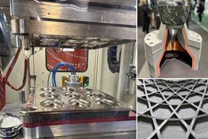
Figure 5. (a) Three coupler parts were made in one set of matched molds that featured (b) springs in the center to keep tension on the laminates during stamp forming. Preheated TPC sheets were placed into the mold set in (c) an injection molding press where they were stamp formed into (d) double-curved parts that were then trimmed and ready for welding to frames. Source | Aitiip
Three parts were press formed in the same mold with 4 minutes of lamp heating + 10 seconds for closing + 3 minutes cooling for crystallization + 10 seconds of opening for demolding for a cycle time of less than 8 minutes. This not only makes production quicker, says Monzón, “but also helps to maintain symmetry between the bending forces during molding, which makes the process viable. As you can see in the parts [Fig. 5], there was not just one curvature — some of the areas had two or three different curvatures, so the geometry was quite complex. It wasn’t possible to just bend the sheets without wrinkles or distortions — there would be areas with a lack of material or excess material in these curvatures. So, we dealt with this by using springs in the center of one mold half [Fig. 5] that were able to keep tension in the part throughout the process, which prevented wrinkling.”
The parts were cooled in the mold to below glass transition temperature (147°C) and then removed. A six-axis robotic milling machine was used to extract and trim the three parts to their final tolerances. Monzón says this process reduces the cycle time by more than 50% compared to traditional thermoset composite parts, doubling production with a minimal investment in manufacturing equipment.
MFFD completion, follow-on projects
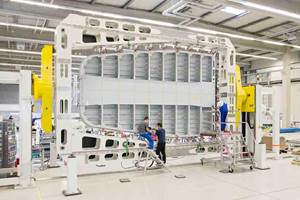
Figure 6. The MFFD with welded assembly completed. Source | Airbus
The major welding operations for the closure of the MFFD were completed with precision and sufficient time to install final local parts before the July 2023 milestone of transporting it to the ZAL Centre for Applied Aviation Research GmbH in Hamburg (Fig. 6), says Wölcken. “This milestone was only achieved thanks to the extreme dedication and collaborative mindset of the people in the various MFFD project consortia and the amazing work of the WELDER and MultiFAL consortia together with Fraunhofer IFAM and Airbus.”
At ZAL, the MFFD moved to its next stage as a demonstrator for Clean Sky’s NextGen Cabin and Cargo concept that standardizes the interfaces between the airframe and the customized cabin and systems components. This included a new “Crown Module” comprising the ceiling area and “hat-rack” as well as electrical, air conditioning and oxygen supply components and numerous mechanical fixings. Pre-assembled and installed into the fuselage in a single attachment step, the was constructed with ultra-light rods made from Teijin Carbon Europe (Wuppertal, Germany) TPUD HT CF-PPS thermoplastic slit tape in combination with (Enschede, Netherlands) recycled Spiral light PPS CF40 compound. These adjustable length rods are a great example of how TPC parts production waste can be reused in TPC airframe systems.
“The MFFD continues to be assessed and is the source for further work and inspiration in numerous follow-up projects and initiatives,” says Wölcken. These include FASTER-H2, PENELOPE (EU Horizon 2020 project), ZEUS and HESTIA, the latter part of the German-funded LuFo aviation research program. “The MFFD is a good example of using a major spearhead project to demonstrate a high number of individual CFRTP technologies — and in some cases, even technology variants — with respect to their potential. Subsequently, some of these individual technologies were selected for further, highly driven development. For example, the LuFo HESTIA project contains, among others, key development bricks for the high-rate production of large, complex fuselage frame structures.”
“The WELDER project exemplifies how innovative manufacturing technologies can enhance both structural integrity and sustainability in aerospace,” says Monzón. “By leveraging thermoplastic composites and reducing cycle times, the team achieved significant efficiency gains while minimizing resource consumption. Furthermore, this approach democratizes the use of composite materials by making their production more accessible and cost-effective, while also facilitating their recyclability and reusability. This not only improves manufacturing throughput but also aligns with the industry’s goals for environmentally conscious and circular production systems.”
Related Content
JEC World 2024 highlights: Thermoplastic composites, CMC and novel processes
CW senior technical editor Ginger Gardiner discusses some of the developments and demonstrators shown at the industry’s largest composites exhibition and conference.
Read MoreFrom the CW Archives: Airbus A400M cargo door
The inaugural CW From the Archives revisits Sara Black’s 2007 story on out-of-autoclave infusion used to fabricate the massive composite upper cargo door for the Airbus A400M military airlifter.
Read MoreDevelopment of a composite liquid hydrogen tank for commercial aircraft
Netherlands consortium advances cryogenic composites testing, tank designs and manufacturing including AFP, hybrid winding, welding of tank components and integrated SHM and H2 sensors for demonstrators in 2025.
Read MorePlant tour: Daher Shap’in TechCenter and composites production plant, Saint-Aignan-de-Grandlieu, France
Co-located R&D and production advance OOA thermosets, thermoplastics, welding, recycling and digital technologies for faster processing and certification of lighter, more sustainable composites.
Read MoreRead Next
Welding is not bonding
Discussion of the issues in our understanding of thermoplastic composite welded structures and certification of the latest materials and welding technologies for future airframes.
Read MoreDetermining steel/composite failure load of bonded repair assemblies
Bureau Veritas and partners use a novel equivalent interface test specimen and simulation to predict failure load in bonded composite patch repairs to steel structures.
Read MoreThe potential for thermoplastic composite nacelles
Collins Aerospace draws on global team, decades of experience to demonstrate large, curved AFP and welded structures for the next generation of aircraft.
Read More

