WoundSIM software tool simplifies design and simulation of composite pressure vessels
Rapid and efficient tank design process is achieved via an integrated FEA software translator, advanced parametric optimization, simulation and load case testing and post-processing capabilities.


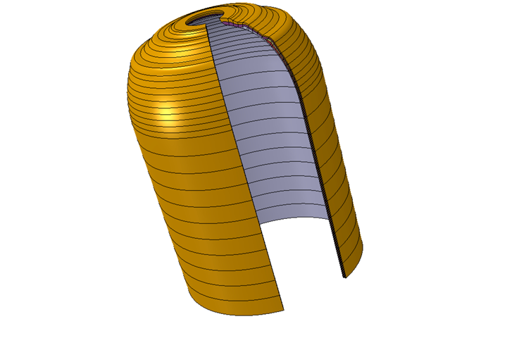
COPV tank model. Photo Credit, all images: S Vertical, QustomApps
WoundSIM is a new software tool targeting the design, simulation and optimization of composite-overwrapped pressure vessels (COPVs). While it is primarily used in the automotive and aerospace industries, it has gained usage with the U.S. Navy, various research centers, the education sector and for hydrogen storage as a rapid and efficient tank design process. It is developed, supported and maintained by Dassault Systèmes (Vélizy-Villacoublay, France) Simulia development partners QustomApps (Ponder, Texas, U.S.) and S Vertical (Châtenay-Malabry, France). The first beta version was released in 2019, with additional features to be included in 2022.
Under WoundSIM, a graphical interface is used to instantaneously view the composite layup as the table of composite layers is defined. Layer thickness buildup is automatically calculated, along with the varying wind angles. Smeared material properties are also computed and assigned throughout the COPV, and an integrated finite element analysis (FEA) software translator enables users to generate a run-ready FEA model to assess the thermal and mechanical responses of the COPV.


Principle WoundSIM features noted include:
- Enhanced layer thickness buildup for better correlation against geometry of produced tanks;
- Comprehensive design parameters enabling a quick variation of layer shape;
- A comprehensive, standalone user interface;
- GUI short time response (<1 sec/30 layers);
- Smart layup rendering for easy layer selection and identification;
- Rapid, fully automated tank FE model generation and post-processing;
- Full compatibility with Dassault Systèmes’ Simulia Abaqus Unified FEA;
- Automated Abaqus WCM models conversion;
- Compatibility with Simulia Isight for advanced parametric optimization;
- Public XML API to ensure compatibility with other winding software or customer’s in-house tools and formulations;
- Integrated tank parametric optimization capabilities to reduce tank weight;
- And integrated models VS tests calibration.
After the layup definition and visualization in the WoundSIM interface, users can generate the reservoir geometry and the corresponding FEA models in order to perform all needed simulations. Generated models include tank layer geometry and enhanced reservoir mesh generation; transformed material properties; automated assembly with other reservoir components; loads and boundary condition definitions; and the possibility to generate 2D, 3D, shell and solid models. Abaqus/CAE models can also be edited and enriched by the user.
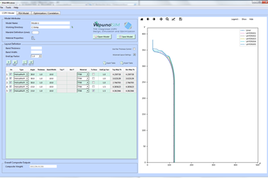
WoundSIM graphical user interface (GUI).
All required load cases to design the tank can be run on the generated FE models, including static/dynamic burst pressure, heat transfer analysis, coupled temperature displacement, dynamic drop tests and impacts and cyclic and fatigue assessment. Fail stress and fail strain parameters can also be included in the FE analysis for a realistic prediction of composites layers failure.
Moreover, the WoundSIM-to-Abaqus interface provides a number of seamless post-processing capabilities such as specialized path plotting and contour plotting tools for quick tank response assessment. WoundSIM includes a compiled user subroutine library that gives access to all composite-specific output post-processing quantities such us winding angles, fiber matrix stresses and strains and damage parameters.
Finally, WoundSIM offers advanced engineering capabilities and integrated algorithms that allow several capabilities for composite reservoir designers and simulation engineers. Some capabilities involve parametric design, Design of Experiment, batch computing, reservoir geometry variability study, correlation to other winding software, models correlation with produced reservoirs and reservoirs images processing.
View for more information on WoundSIM.
Related Content

Optimized rib-reinforced hollow composites via printed molds
Addyx topology optimization and water-soluble mandrel enables simultaneous rib and skin layup for one-shot, high-strength, lightweight structures.
Read More
Cutting 100 pounds, certification time for the X-59 nose cone
Swift Engineering used HyperX software to remove 100 pounds from 38-foot graphite/epoxy cored nose cone for X-59 supersonic aircraft.
Read More
Automated robotic NDT enhances capabilities for composites
Kineco Kaman Composites India uses a bespoke Fill Accubot ultrasonic testing system to boost inspection efficiency and productivity.
Read More
ASCEND program completion: Transforming the U.K.'s high-rate composites manufacturing capability
GKN Aerospace, McLaren Automotive and U.K. partners chart the final chapter of the 4-year, £39.6 million ASCEND program, which accomplished significant progress in high-rate production, Industry 4.0 and sustainable composites manufacturing.
Read MoreRead Next

Scaling up, optimizing the flax fiber composite camper
Greenlander’s Sherpa RV cab, which is largely constructed from flax fiber/bio-epoxy sandwich panels, nears commercial production readiness and next-generation scale-up.
Read More
Next-gen fan blades: Hybrid twin RTM, printed sensors, laser shock disassembly
MORPHO project demonstrates blade with 20% faster RTM cure cycle, uses AI-based monitoring for improved maintenance/life cycle management and proves laser shock disassembly for recycling.
Read More
Ceramic matrix composites: Faster, cheaper, higher temperature
New players proliferate, increasing CMC materials and manufacturing capacity, novel processes and automation to meet demand for higher part volumes and performance.
Read More