Resin transfer molding: An update
Fulfilling the promise of OOA composites without sacrificing pressure.
Although the origins of resin transfer molding (RTM) reach back to post-World War II marine vessel development in the 1950s, the process was not applied to aerospace composites until the 1980s. RTM has two primary advantages over resin infusion. One is its application of high pressure — typically up to 100 psi, vs. 14.7 psi with vacuum only — although RTM equipment can generate pressures above 300 psi. The other is its use of matched metal molds, which enable tight tolerances, complex geometries and a high-quality finish on all visible molded surfaces. Its disadvantages include mold and injection equipment cost and process complexity, but with continuing advances in simulation tools, the latter is being addressed while the equipment, costly though it might be, offers a route to automation and holds a definite edge over infusion in terms of part repeatability.
Advanced Composite Engineering GmbH (ACE, Immenstaad, Germany), for example, is manufacturing the Airbus (Toulouse, France) A350 XWB’s carbon fiber composite window frames, using an automated RTM production line supplied by mold manufacturer BBG GmbH & Co. KG (Mindelheim, Germany). BBG reports that the line installed at ACE’s facility in Hagnau, Germany, can produce up to 8,000 composite window frames per year using the current twin BFT-C mold carrier systems (see "Airbus A350 to use CFRP window frames" under “Editor's Picks,” at top right). Addition of four more BFT-C systems is planned, presumably for production rate increase.
Originally developed for the Airbus A380, the frames met a challenge to reduce weight while meeting precise geometry and primary fuselage loads as well as cost targets. The A350 frames use a complex 3D preform developed by Hightex Verstärkungsstrukturen (Klipphausen, Germany) and Airbus Operations in Hamburg, Germany. Tailored Fiber Placement (TFP, see "Tailored Fiber Placement: Besting metal in volume production" under “Editor's Picks”) is used to create a 2D preform with both selective stitching (stitches in some areas and not in others) and structural stitching (straight up-and-down stitches), as well as a glass fiber interior lining to prevent galvanic corrosion with aluminum interfaces (see Fig. 1, at left). As the flat TFP preforms are shaped into a wrinkle-free oval with an L-shaped cross-section, selective stitching allows the fibers to conform while maintaining straight alignment to carry loads, while structural stitching assists in handling the high loads around the frame’s circumference.
Elsewhere, Aernnova Aerospace (Madrid, Spain) is using RTM to produce the leading edge and its load-bearing rib for the A350 XWB’s horizontal tail plane (HTP, or horizontal stabilizer). Reportedly the only Tier 1 supplier to include RTM in its bid for the design, validation, manufacture and assembly of the A350 HTP, Aernnova used ESI Group (Paris, France) PAM-FORM software to simulate preforming, including fiber angles that affect permeability, and PAM-RTM software to simulate resin injection and filling of the preform. Together, the programs helped Aernnova eliminate preform wrinkles, add new vent points to eliminate dry spots and modify the RTM mold to ensure part quality and process reproducibility.
Airbus Helicopter’s Donauwörth, Germany, facility is also molding RTM structures for the A350 XWB, i.e., the inner structural grid for each aircraft’s four pairs of passenger doors (click on "Donauwörth as composites pioneer" under “Editor's Picks”). A Wickert Hydraulic Presses USA (Landau in Pfalz, Germany) W WKP 2500 S press with a 2500-kN closing pressure and automatic shuttle transport is used to cure preconsolidated preforms made from 3C-Carbon Composite Co. (Landsberg am Lech, Germany) carbon fiber fabrics injected with Hexcel’s (Stamford, CT, US) HexFlow RTM6 epoxy. WICKERT reports a six-hour cure cycle per door.
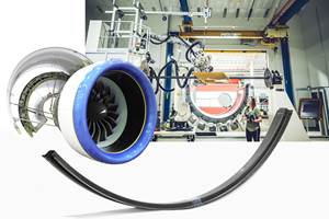
Other parts using RTM (see "Reducing manufacturing cost via RTM" under “Editor's Picks”) include the main fitting (see Fig. 2) for spoilers used on the Airbus A330/A340 and now, refined for the A350 XWB by FACC (Ried im Innkreis, Austria); fan blades and the fan case for CFM International’s (Cincinnati, OH, US) LEAP jet engine; the main landing gear braces for the Boeing 787 (now reverted to metal) made by Aircelle’s Le Havre, France, facility for Messier-Dowty (Velizy, France) using Albany Engineered Composites Inc. (AEC, Rochester, NH, US) 3D textile preforms; and a variety of structures on the F-35 Lightning II fighter built by Lockheed Martin Aeronautics(Ft. Worth, TX, US), GKN Aerospace(Redditch, UK) and others.
Related Content
Revisiting the OceanGate Titan disaster
A year has passed since the tragic loss of the Titan submersible that claimed the lives of five people. What lessons have been learned from the disaster?
Read MorePlant tour: Teijin Carbon America Inc., Greenwood, S.C., U.S.
In 2018, Teijin broke ground on a facility that is reportedly the largest capacity carbon fiber line currently in existence. The line has been fully functional for nearly two years and has plenty of room for expansion.
Read MoreComposites end markets: New space (2025)
Composite materials — with their unmatched strength-to-weight ratio, durability in extreme environments and design versatility — are at the heart of innovations in satellites, propulsion systems and lunar exploration vehicles, propelling the space economy toward a $1.8 trillion future.
Read MoreThe potential for thermoplastic composite nacelles
Collins Aerospace draws on global team, decades of experience to demonstrate large, curved AFP and welded structures for the next generation of aircraft.
Read MoreRead Next
Research on OOA processing continues
Much work has been done to make OOA processing practical for aerospace applications, but much work still remains if it is to become the compelling option.
Read MoreScaling up, optimizing the flax fiber composite camper
Greenlander’s Sherpa RV cab, which is largely constructed from flax fiber/bio-epoxy sandwich panels, nears commercial production readiness and next-generation scale-up.
Read More


