Addcomposites' virtual demo on how to make an AFP composite laminate
Readers are walked through how to program and operate the AFP-XS plug and play system.


Witnessing the entire process of digitized composite layup usually requires you to travel and visit the facility where the AFP/ATL systems are running. This blog post by Addcomposites walks you through a virtual demo video experience, showing how to program and operate the company’s compact, plug and play AFP-XS system for producing composite products or shapes.
Object to Lay
For the very first demo, we are starting with a really basic rectangular shape. The rectangle base laminate is 400 × 450 millimeters in size with a central patch laminate of 100 × 150 millimeters.


- The base laminate has the fiber orientation of [0 degrees / 90 degrees /+45 degrees /-45 degrees]
- The central patch laminate has an orientation of [+45 degrees / -45 degrees].
- The total six-layer laminate has to be laid without any overlaps in the fiber and the maximum gap allowed was 1 millimeter.
Off-Line Programming: ADDpath
The ADDpath software is a plug-in on top of commonly used CAD modeling platform Rhino. The key feature of creating the planning software with this approach provides:
- Accessibility : The ADDpath was built with the goal of accessibility and customization in mind. The open platform allows for different material uses, layup techniques, fiber paths, and mold shapes to be used.
- Fast setup: ADDpath requires minimal installation time, and since most universities/R&D centers/technical clusters have existing Rhino subscriptions, there is no additional learning curve or infrastructure investments.
- Freedom: The Rhino ecosystem allows for visual programming elements, that can be implemented on top of the ADDpath generated programs.
Process
The programming process is quite intuitive in its nature, and following these simple steps will ensure success.
- Import the CAD file in .stp format to ADDpath.
- Start with adding the lay-up sequence [0 degrees / 90 degrees / +45 degrees / -45 degrees] for the base layer
- Check for the Layup and Speed parameters
- Click on "Add Layup" and select the base surface. Now you can see Layup 1 appears in the layup window.
- Enter the layup sequence for the central patch laminate [+45 degrees / -45 degrees].
- Click on “Add Layup” and select the central patch surface. Now you can see Layup 2 appears in the layup window.
- To finalize the layup, click on “Plan Layup.” This brings up the material needed for the layup and the time estimate to do the layup.
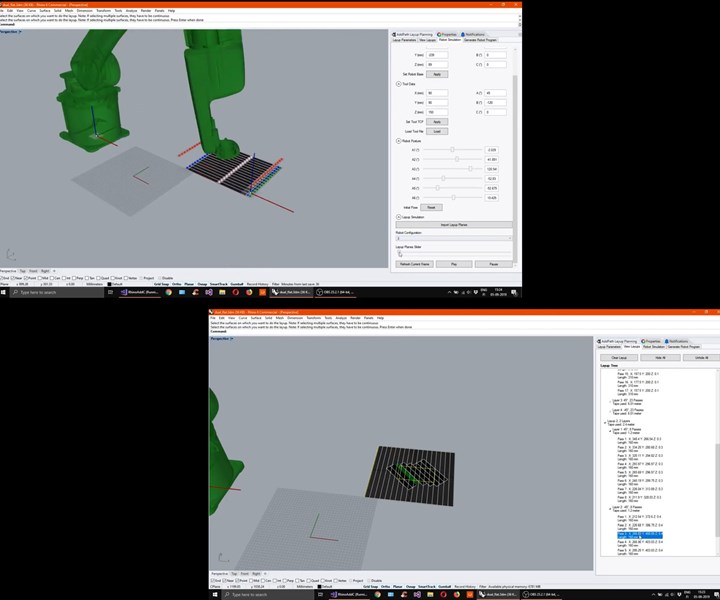
- Now we can visualize the planned layup, through the layup tree. Here you have option to suppress individual passes, visualize individual layers, and more.
- Now we move onto the Simulation stage, where we see the robot (requiring only an initial upload, then is available each time thereafter) appears and simulates the layup of each pass. Presently the robot will turn pink if it is hitting any soft limits, and red if it hits a hardware limit. The upcoming version will have collision detection between the AFP-XS and mold as well.
- During the Visualization you can slide through the frames of robot motion to ensure smooth operation in virtual environment. This helps in optimizing the operations and accident avoidance during actual operation. Alternatively, you can hit “Play” to see a full animation of your layup.
- Once satisfied with your simulation and layup, click “Generate Robot Program.” This will create code in the specified robotic language. This is currently available for KUKA, for which you can use the OrangeEdit application to visualize the generated program. Save the generated program to your USB drive, and then transfer it to the KUKA control box.
To read the whole blog with videos go to:
Related Content

Revisiting the OceanGate Titan disaster
A year has passed since the tragic loss of the Titan submersible that claimed the lives of five people. What lessons have been learned from the disaster?
Read More
Composites end markets: New space (2025)
Composite materials — with their unmatched strength-to-weight ratio, durability in extreme environments and design versatility — are at the heart of innovations in satellites, propulsion systems and lunar exploration vehicles, propelling the space economy toward a $1.8 trillion future.
Read More
Plant tour: Airbus, Illescas, Spain
Airbus’ Illescas facility, featuring highly automated composites processes for the A350 lower wing cover and one-piece Section 19 fuselage barrels, works toward production ramp-ups and next-generation aircraft.
Read More
Welding is not bonding
Discussion of the issues in our understanding of thermoplastic composite welded structures and certification of the latest materials and welding technologies for future airframes.
Read MoreRead Next

Next-gen fan blades: Hybrid twin RTM, printed sensors, laser shock disassembly
MORPHO project demonstrates blade with 20% faster RTM cure cycle, uses AI-based monitoring for improved maintenance/life cycle management and proves laser shock disassembly for recycling.
Read More
Ceramic matrix composites: Faster, cheaper, higher temperature
New players proliferate, increasing CMC materials and manufacturing capacity, novel processes and automation to meet demand for higher part volumes and performance.
Read More
Ultrasonic welding for in-space manufacturing of CFRTP
Agile Ultrasonics and NASA trial robotic-compatible carbon fiber-reinforced thermoplastic ultrasonic welding technology for space structures.
Read More