AniForm, Moldex3D develop interface tool for more accurate RTM prediction analysis
Interface enables users to consider forming-induced fiber reorientation in the RTM simulation model for a more accurate representation of the flow domain.


All photo credit: AniForm, Moldex3D
(Enschede, Netherlands), an advanced simulation tool that predicts the formability of composite laminates, is collaborating with (St. Zhubei City, Taiwan) to enable users to run more accurate resin transfer molding (RTM) analyses. With this new interface, workflow has been improved to smoothly import the fiber reorientation data (recorded as an ASCII file) from AniForm Suite and run the RTM simulation with Moldex3D’s simulation tools. Additionly, input accuracy for the RTM model has been optimized and RTM simulation results made more accurate.
“AniForm strives to deliver a software tool that enables engineers to focus on the analysis of a prediction, rather than spending too much time on modeling and data transfer between various simulation tools,” says Sebastiaan Haanappel, managing director at AniForm. “Moldex3D is a renowned partner in the industry, so we were thrilled to cooperate with them. We were very happy with this collaborative effort, which led to a seamless interface between our tools.”


When coming up with the solution, both AniForm and Moldex3D focused on targeting the following challenges:
- Lack of a seamless workflow between the different simulation tools;
- The fiber orientations in a fabric change significantly during forming;
- Fabric shear and fiber reorientation locally affects the magnitude and orientation of the fabric’s permeability property.

To address these, a case study was performed, with the main objective to compare the different results between two models; one that directly assigned an assumed orthogonal fabric orientation, and one that considered the fabric orientation result from an AniForm forming prediction. The goal was to see how different inputs can have a significant impact on the resin infusion simulation results.
First, AniForm’s team generated a simulation of a woven fabric forming that was then used as an input in Moldex3D software for the fabric orientation. The fabric simulation was exported as an ASCII file from AniForm and imported in Moldex3D to run the RTM simulation.
Then, the part was created. A laminate consisting of five fabric layers with a [(0/90)]5 layup was formed into a mold cavity, which represents the final part shape. Subsequently, the mold itself was heated and injected with resin, with a final part released after curing. This part was referred to as the Formed Woven Fabric (Fig. 2).
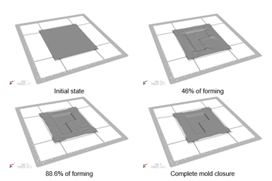
Fig. 3. AniForm forming predictions at various instances.
To take into consideration the forming induced fabric distortions in a subsequent infusion simulation in Moldex3D, a composite forming simulation in AniForm was performed. Fig. 3 shows the predicted laminate deformations at various instances during the forming. These deformations led to the resulting in-plane shear distribution and related fiber re-orientation at complete mold closure in the final step as shown in Fig 4.
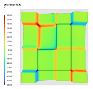
Fig. 4. Shear angle distribution predicted by AniForm.
Two infusions model configurations were created in Moldex3D (see Fig. 5). The first model assumes the fabric still to be orthogonal, namely 0º and 90º in every part (light blue: 0º, dark blue: 90º). However, Moldex3D and AniForm note that, in reality, an orthogonal fiber orientation will not be present since the forming leads to in-plane fabric deformation, meaning the fabric orientation will no longer be 0º and 90 in every part. Therefore, the second model considers the forming results from AniForm, using the forming induced fiber-reorientation. Because the fiber reorientation affects permeability (indicated in Fig. 6), Moldex3D and AniForm believe the second model to result in a more accurate representation.

Fig. 5. Fabric orientation.

Fig. 6. Flow front.
Thus, the case study concluded that the developed interface, improving the estimation of the flow progression over time, enables engineers to better anticipate changes in the process configuration and production cycle durations, as well as a higher degree of confidence when analyzing and interpreting the results.
“We are delighted to cooperate with AniForm, which is undoubtedly a remarkable player in our industry,” says Dannick Teng, managing director at Moldex3D. “This is the first step of Moldex3D and AniForm’s collaboration, and we are both looking forward to further integration soon.”
For more information, please contact support.eu@moldex3d.com or info@aniform.com
Related Content

Plant tour: BeSpline/Addcomp, Sherbrooke, QC, Canada
Composites automation specialist increases access to next-gen technologies, including novel AFP systems and unique 3D parts using adaptive molds.
Read More
Bladder-assisted compression molding derivative produces complex, autoclave-quality automotive parts
HP Composites’ AirPower technology enables high-rate CFRP roof production with 50% energy savings for the Maserati MC20.
Read More
Carbon fiber, bionic design achieve peak performance in race-ready production vehicle
Porsche worked with Action Composites to design and manufacture an innovative carbon fiber safety cage option to lightweight one of its series race vehicles, built in a one-shot compression molding process.
Read More
Cutting 100 pounds, certification time for the X-59 nose cone
Swift Engineering used HyperX software to remove 100 pounds from 38-foot graphite/epoxy cored nose cone for X-59 supersonic aircraft.
Read MoreRead Next

Next-gen fan blades: Hybrid twin RTM, printed sensors, laser shock disassembly
MORPHO project demonstrates blade with 20% faster RTM cure cycle, uses AI-based monitoring for improved maintenance/life cycle management and proves laser shock disassembly for recycling.
Read More
Scaling up, optimizing the flax fiber composite camper
Greenlander’s Sherpa RV cab, which is largely constructed from flax fiber/bio-epoxy sandwich panels, nears commercial production readiness and next-generation scale-up.
Read More
Cutting 100 pounds, certification time for the X-59 nose cone
Swift Engineering used HyperX software to remove 100 pounds from 38-foot graphite/epoxy cored nose cone for X-59 supersonic aircraft.
Read More