Big machines, small tolerances
An examination of the lengths Janicki Industries (Sedro-Woolley, Wash.) goes to ensure dimensional precision in its massive CNC-machining operations.
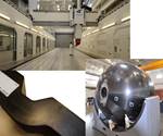
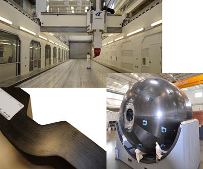
To accommodate the ever-increasing size of composite parts and the tools they require, Janicki Industries (Sedro-Woolley, Wash.) installed twin CNC mills, #5 and #6, in its Hamilton, Wash., facility. Among the largest in the world, the 100-ft by 20-ft by 8-ft (30.5m by 6m by 2m) machines were integrated into the facility as it was built. Specially designed reinforced concrete floors were poured to support the CNC machine gantries. The building was erected around them.
Massive filtration systems were developed to efficiently remove cutting debris and dust on large projects. Because the mills ride on 120-ft/36.6m steel rails, a temperature-induced change in dimensions can be problematic. (The linear CTE for steel at room temperature averages roughly 6x10⁻⁶ per 1°F (12x10-6 per 1°C), which produces a length change of 9 mils/0.2 mm per degree in a 120-ft/37m long rail.) For that reason, the temperature of the overall facility is held to within ±5°F/±3°C of the set point, and the CNC mill rooms are kept within ±1°F/±0.6°C of the set point.
CNC mill operations manager Eric Friesen claims that accuracy is what differentiates Janicki. “Despite the many CNC mill compensation systems available in the industry, we continue to write our own,” he points out. “The compensation systems you can buy simply do not work well on mills of this size and complexity.” Those systems assume certain mechanical accuracies in the machine, but Janicki prefers to measure and account for possible error instead. Friesen credits this attention to detail to Dr. John Weller, who runs the Automation and Mechatronics department at Janicki Industries. “He and his team of engineers have translated a 5-axis CNC mill into a huge mathematical problem, and then developed proprietary software to solve it with four- and five-decimal-place accuracy.”
The mill, as it glides on the rails, forms the x-axis, the carriage moves back and forth across the bridge in the y-axis, the mast moves up and down on the z-axis and the machine head “wrist” articulates and rotates, making up the final two axes. Compensation for inaccuracies is developed by “clocking in” the CNC machine.
“We mount a laser tracker in the head of the machine spindle and track its movement, using multiple lasers triangulating on its position as it moves through its volumetric envelope,” Weller explains. “We then use that data and our proprietary algorithms to solve a massive nonlinear system of simultaneous equations with millions of unknown coefficients. The hardware and software in modern computers make this possible and relatively easy. We have a program that takes the measurements automatically in a few hours, coordinating the movement and communication of the laser equipment and the mill. Then the math is solved on a PC in the controller in a few minutes and, presto! … we have a dead-accurate CNC mill in five full degrees of freedom to around ±0.002 inches. This is an astonishing feat for machines that are large enough to produce tooling for wind turbine blades or wings on commercial aircraft.”
Another example of this accuracy is geometric tolerancing of holes. For Lockheed Martin’s F-35 parts, the accuracy of the hole centerline had to be within a 0.007-inch/0.178 mm diameter cylinder (on the scale of human hair). Over a period of more than two years, Janicki claims it has drilled more than 500,000 holes in F-35 components within this tolerance without a miss. During HPC’s tour, Friesen showed a machined structure that had to meet a surface flatness and roundness of profile tolerance of ±5 mils (0.005 inch/0.127 mm) — the thickness of a sheet of paper. “When you get this low in surface deviation,” he notes, “you have to blow the dust off the surface before you take measurements or it throws you off. Right now, the degree of accuracy of our mills is bumping up against our ability to measure it. So we are as accurate as can be measured.”
Why such attention to accuracy? CEO Peter Janicki replies, “In the end, our customers get accurate tools that produce accurate parts.” Accurate parts cascade benefits throughout the program. A reduction in hand sanding and finishing saves much time and cost during assembly. “It also results in superior cosmetic surfaces,” he adds, pointing out that “the more someone sands and polishes on a tool, the further away it gets from the original intent of the CAD model, modifying subtle feature lines and other details.”
Related Content
Composites reinvent infrastructure
Celebrating National Composites Week, CW shares ways in which composites continue to evolve the way we approach infrastructure projects.
Read MoreWoven UD fabric enhances scalable carbon fiber options for infrastructure
CAMX 2025: Zoltek introduces PX35 woven UD fabric which bridges the gap between performance and affordability for retrofit and new build scenarios.
Read MoreR-Tech Materials offers accredited composite rebar testing
The independent U.K. lab has has developed a comprehensive suite of materials testing capabilities tailored to the growing demands of the construction sector.
Read MoreBrainDrip scales up composite technology to meet current, future energy infrastructure needs
Next-generation composite pipe development with embedded, AI-enhanced health monitoring will modernize new and aging pipelines globally.
Read MoreRead Next
Janicki Industries: Breaking the mold
Once known only as a toolmaker, Janicki offers unique precision, production capability and problem solving as it pioneers leading-edge composites technology.
Read MoreNext-gen fan blades: Hybrid twin RTM, printed sensors, laser shock disassembly
MORPHO project demonstrates blade with 20% faster RTM cure cycle, uses AI-based monitoring for improved maintenance/life cycle management and proves laser shock disassembly for recycling.
Read MoreScaling up, optimizing the flax fiber composite camper
Greenlander’s Sherpa RV cab, which is largely constructed from flax fiber/bio-epoxy sandwich panels, nears commercial production readiness and next-generation scale-up.
Read More


